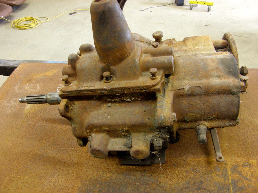

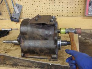
It’s time to reassemble the Spicer three-speed gearbox

Last time around we began a repair on an older, typical three-speed transmission, the kind you’d find in a classic farm pickup truck. While all three-speed transmissions of that era have their own unique components, their overall designs are very similar. This rebuild is typical of what would be necessary on any similar three-speed.
Even though most people might think of sending out a transmission to a specialty shop for a rebuild, it’s possible to do a major repair right in the farm workshop. However, having a good shop service manual and doing a little research on the exact procedure is necessary before starting the job. This look at the process will give you a good idea of what’s involved in the final step of the rebuild process.
Step 1: Ready for reassembly
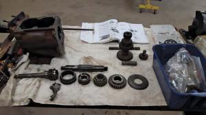
With all of the original parts cleaned up, they were laid out on the workbench to be checked. Careful observers will notice the synchronizer rings are missing from this image. They needed replacement. A complete synchronizer assembly was ordered to replace the original.
Most of the gears and all the shafts were okay, but the cluster gear didn’t fare too well sitting in the water that filled the bottom of the transmission case. So a new one of those was ordered as well.
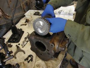
Step 2: Comparing parts
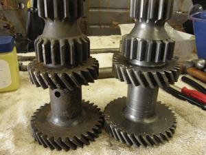
When the replacement cluster gear arrived, it was compared to the original. It’s a good thing that was done, because the new cluster gear was an incorrect part. The main gear had two extra teeth giving it a larger diameter. It was a change-up part for later-year transmissions. We had to re-order the correct one.
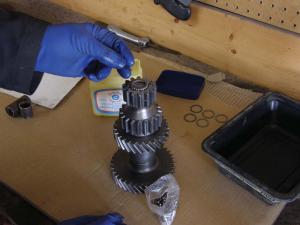
We compared the synchronizer assembly to the original and it was correct, but it arrived fully assembled and we just assumed it was put together properly. When it was installed on the shaft, one synchronizer ring was left flopping loosely. We spent a lot of time head scratching and reviewing the shop manual because of that. It turned out the manufacturer put the assembly together incorrectly. After we made the necessary change, everything fit together fine.
Step 3: Needles and bearings
The Spicer transmission uses needle bearings in two places, four sets inside the cluster gear (shown) and one in the end of the input shaft. All the bearings need to be installed one at a time. But it isn’t as daunting a task as it might seem.
A temporary shaft replacement was placed inside the gear along with the centre spacer and one of a series of temporary spacers we created to do the job. The needle bearings were then inserted into each end of the gear using petroleum jelly to hold them in place and create a temporary lubricant. Do not use regular grease for any of the assembly processes on a transmission, it doesn’t break down quickly enough inside the gear oil.
Step 4: A special tool
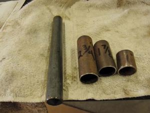
Here’s the basic installation tool we made for the needle bearing installation job. It just consists of a shaft the exact length of the cluster gear and three pieces of metal tubing of different lengths to hold the centre spacer in the right position as each set of needle bearings is inserted.
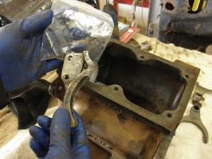
Step 5: Thrust washers
Now that the cluster gear is loaded with bearings and ready to install, the thrust washers that hold it in place inside the case were also coated with petroleum jelly. That will hold them in place inside transmission case as parts are installed.
Step 6: Cluster gear installation
With the temporary replacement shaft still inside the cluster gear, it is inserted in the case and positioned between the two thrust washers. If you’re careful the needle bearings will likely stay in place during this process without leaving that short shaft in. But this guarantees it. The counter shaft the gear spins on isn’t installed just yet. That allows the cluster gear to drop to the bottom of the case leaving enough room to get the other two shafts to fit in.
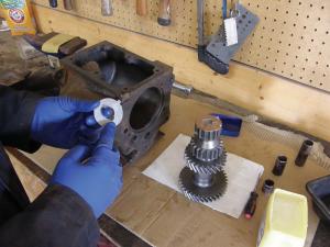
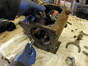
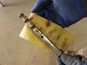
Step 7: Oil collector
The input shaft is installed by simply tapping its bearing into the opening in the front of the case. The oil collector, which directs lubricant up to the input shaft bearing, is installed at this point.
Step 8: Reverse idler gear
The small reverse idler gear and the short shaft it runs on get installed now.
Step 9: Main shaft
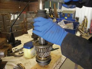
Using a large socket and a hammer, the rear main shaft bearing is installed on the shaft after it is fully assembled. It’s now ready to go into the case. Once the needle bearings are installed in the end of the input shaft, the main shaft is inserted through the rear of the case and into position with the front of the main shaft riding on those needle bearings.
Step 10: Countershaft installation
With the transmission case turned upside down, the cluster gear now falls into place by gravity, meshing with the main and input shafts. Taking care to make sure the thrust washers are in place (use a small screwdriver inserted through the case shaft openings to move them if necessary) the countershaft is tapped through the case and gear. This causes the temporary shaft that holds the needle bearings secure to get pushed out the front of the case.
Step 11: Shift rails
Because our Spicer has a top shifter position, rather than side linkages for a “three-on-the-tree” shift lever, the shift rails are in the top cover. They were removed from the cover and cleaned with sand paper to ensure they would slide smoothly in the cover housing.
Step 12: Finishing up the shift linkage
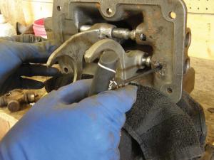
Each shift rail has a poppet ball under spring pressure that rides on it to hold the linkage into each gear position. After inserting new poppet balls and springs, an Allen wrench was used to push on the balls and compress the springs behind them as the shift rails were slid back into place.
With that job done the shift forks can be slid into place on the main shaft as the top cover is reinstalled. And that’s it. Job done. The transmission is ready to be bolted back up to the transfer case and bell housing.